
How To Set Up Lane-By-Lane Vehicle Counting Zones With An AI Camera
By the end of this guide you will have one AI camera producing separate vehicle counts for every lane and both directions of travel, with merge and turn lanes handled, checked against a manual count. Expect about half a day on site for positioning and configuration, then a few hours of validation spread across peak, off-peak and night periods.
Read As Text
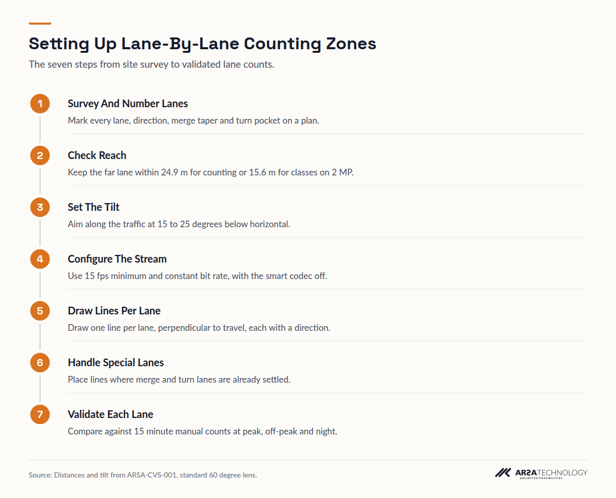
- Survey And Number Lanes Mark every lane, direction, merge taper and turn pocket on a plan.
- Check Reach Keep the far lane within 24.9 m for counting or 15.6 m for classes on 2 MP.
- Set The Tilt Aim along the traffic at 15 to 25 degrees below horizontal.
- Configure The Stream Use 15 fps minimum and constant bit rate, with the smart codec off.
- Draw Lines Per Lane Draw one line per lane, perpendicular to travel, each with a direction.
- Handle Special Lanes Place lines where merge and turn lanes are already settled.
- Validate Each Lane Compare against 15 minute manual counts at peak, off-peak and night.
PREREQUISITES
Before You Start
You need a measured site, a camera that can resolve vehicles at the distance you plan to count, and permission to work at the roadside. Check each item before you go out:
- A plan or aerial image of the approach, with every lane numbered and its direction of travel marked, including merge tapers, turn pockets and bus lanes.
- Measured lane widths and the distance from the pole or gantry to the near and far edge of the area you want to count.
- An IP camera of 2 MP minimum (4 MP recommended), 15 fps minimum on the main stream, ONVIF Profile S or RTSP, with WDR of 120 dB or better for headlight glare.
- An outdoor cabinet rated IP66, with IK08 recommended, for the processing unit if it sits at the pole.
- Admin access to the camera's web interface and a free concurrent stream slot. Your existing recorder usually takes one.
- A road authority permit and temporary traffic control for any work at the kerb. In the US, work zones follow Part 6 of the MUTCD. In the UK, Chapter 8 of the Traffic Signs Manual applies.
- A qualified installer for pole work and any electrical connection in the roadside cabinet.
- A second person with a tally counter, or a recorded clip, for validation in Step 7.
Lane-level counts are also what most traffic data programmes expect. The FHWA's 2022 Traffic Monitoring Guide lists volume by lane by hour among the objectives of continuous counting. Agree the lane numbering with whoever will receive the data before you draw a single line.
STEP 1
Step 1: Survey The Approach And Number Every Lane
Walk the approach and confirm that the lanes on your plan match the paint on the road. Number the lanes in a fixed order, for example from the kerb outwards in each direction. Mark where each merge taper begins and ends, where turn pockets open, and where vehicles routinely change lanes.
You can move on when your plan shows a stretch of road in each direction, at least two vehicle lengths long, where every lane is marked with a solid or dashed line and lane changes are rare. That stretch is where your counting lines will go.
STEP 2
Step 2: Choose A Camera Position Within Reach Of Every Lane
Put the camera close enough that every lane you want to count gets the pixel density the analytic needs. Under ARSA's camera and site standard, ARSA-CVS-001, counting needs 67 pixels per metre (PPM) at the target and classification needs 107 PPM. With a standard 60 degree lens, that limits a 2 MP camera to 24.9 m for counting and 15.6 m for classification. A 4 MP camera reaches 33.3 m and 20.8 m.
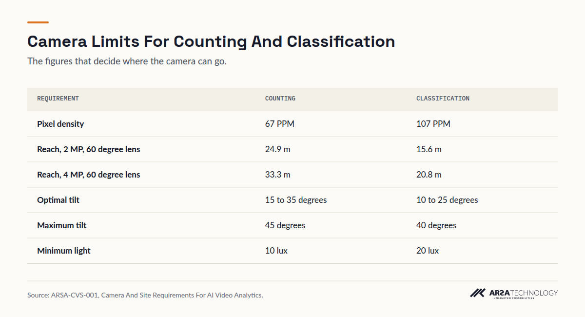
View The Data
| Requirement | Counting | Classification |
|---|---|---|
| Pixel density | 67 PPM | 107 PPM |
| Reach, 2 MP, 60 degree lens | 24.9 m | 15.6 m |
| Reach, 4 MP, 60 degree lens | 33.3 m | 20.8 m |
| Optimal tilt | 15 to 35 degrees | 10 to 25 degrees |
| Maximum tilt | 45 degrees | 40 degrees |
| Minimum light | 10 lux | 20 lux |
Measure to the far edge of the farthest lane, because that is where pixel density is lowest. If you need classes (car, truck, bus, motorcycle, bicycle) in every lane, the classification distance is the one that governs. A 2 MP camera with a 60 degree lens covers a footprint about 11 m wide at 15.6 m, which typically means three lanes. Wider roads need a higher resolution sensor, a narrower lens or a second camera. The Lens FOV Visualizer shows the footprint of a given lens and distance before anyone climbs a pole.
You can move on when the far edge of every lane falls inside the reach for the analytic you need.
STEP 3
Step 3: Set The Tilt Between 15 And 25 Degrees And Aim Along The Traffic
Aim the camera along the direction of travel, looking down at the counting stretch at 15 to 25 degrees below horizontal. That band suits both tasks. Counting is optimal from 15 to 35 degrees (45 maximum), and classification is optimal from 10 to 25 degrees (40 maximum).
You can work out the tilt from geometry: it is the arctangent of mount height divided by the horizontal distance to the centre of the counting stretch. A camera mounted 6 m up and aimed at a point 15 m away sits at about 22 degrees. The same camera aimed at 24.9 m sits at about 13.5 degrees, which is below the optimal band for counting. A steeper view reduces the chance of a truck in the near lane hiding a car in the far lane. Keep to the 40 degree ceiling if you need classes.
You can move on when the live view shows the full width of every lane at the counting stretch, with the gaps between vehicles visible.
STEP 4
Step 4: Configure The Camera Stream For Analytics
Change the stream settings that degrade analytics before you draw any zone, because zones drawn on a badly configured stream will not count reliably. On the analytic stream, set the following:
| Setting | Value For Counting |
|---|---|
| Frame rate | 15 fps minimum, 25 fps recommended |
| Bit rate mode | Constant (CBR) |
| Smart codec (H.264+, H.265+, Zipstream) | Off |
| Minimum shutter | Set manually, so moving vehicles do not smear at dusk |
| Privacy masks, corridor or rotate mode | Off |
| On-camera motion detection and analytics | Off |
| WDR | 120 dB or better where headlights face the camera |
| Time sync | NTP, under one second drift |
| Network, camera to processor | Latency under 20 ms, packet loss under 0.1% |
Pull the stream directly from the camera. NVR re-streams are transcoded, drop frames and are time shifted. You can move on when a fast vehicle appears as a sharp shape in a paused frame.
STEP 5
Step 5: Draw One Counting Line Per Lane, With A Direction
Draw a separate counting line across each lane, perpendicular to travel and running from one lane marking to the next, then set the direction a vehicle must cross it to be counted. Naming each line after its lane number from Step 1 keeps the exported data readable.
Place the lines in the stretch you found in Step 1, in the part of the frame where vehicles appear whole and separated. Avoid placing lines near the frame edges or at the far end of your reach. Stop each line just inside the lane markings, so that a vehicle straddling two lanes crosses one line rather than both. For the opposite carriageway, draw its own lines with the reverse direction. In the Traffic Monitor the counting lines, their directions and the classes counted on each are set in the configuration interface for each camera, as covered in the guide to running traffic analytics on existing CCTV.
You can move on when a vehicle you watch in each lane adds exactly one count to that lane and to no other.
STEP 6
Step 6: Handle Merge, Turn And Shared Lanes
Lanes that appear, disappear or share traffic need their lines placed where each vehicle's lane is already settled. Three cases cover most sites.
Merge Lanes
Put the line upstream of the taper, where the merging lane still has its own marking. Inside the taper, a vehicle can sit across two lanes and you cannot tell which lane it belongs to.
Turn Pockets
Count a turn pocket once it has fully opened and its marking is solid. Before that point, vehicles still changing lanes will be credited to the through lane.
Shared Or Bus Lanes
If the lane carries mixed traffic, count it like any other lane and use classification to separate the buses. Report it as its own lane, so a bus-only rule can be applied in analysis afterwards.
You can move on when a recorded clip of 20 or 30 vehicles through each special lane matches what you counted by eye.
STEP 7
Step 7: Validate Each Lane Against A Manual Count
Count each lane by hand for at least 15 minutes and compare the result lane by lane with the system's count for the same period. Repeat at peak, off-peak and after dark. Recording a clip and counting it at reduced speed is easier than counting live traffic.
Before you begin, agree an acceptable difference with the people who will use the data. Investigate any lane that differs much more than the others: the cause is usually placement or occlusion, and changing a line or the tilt fixes it. Check the light at night. Counting needs at least 10 lux at the target and classification needs 20 lux. Heavy rain degrades classification before it degrades counting. You are finished when every lane is within the agreed difference in all three periods and the result is recorded.
TROUBLESHOOTING
What Goes Wrong And How To Recognise It
Most lane counting faults show up as a pattern between lanes, so compare the lanes with each other before you look at totals. If one lane reads high and its neighbour reads low by a similar amount, vehicles are being credited to the wrong lane. The line probably sits where drivers change lanes, or it crosses the marking. Move the line along the road to where the lane is settled.
The far lane under-counting at busy times while it is accurate when traffic is light points to occlusion: tall vehicles in the near lane hide smaller ones behind them. Increase the tilt toward 25 degrees, raise the mount, or add a second camera facing the other way. If a lane under-counts only after dark, measure the light at the target before you blame the analytics, and look for headlight bloom when WDR is switched off.
When counts drift slowly over weeks, the camera has usually moved. Wind, a maintenance visit or a loose bracket can turn a camera a few degrees, which pushes the lines out of their lanes. Take a reference still at handover and compare it with the live view each quarter. In the ARSA standard, an accuracy figure attaches only to zones accepted at site acceptance, and a moved camera returns its zones to unaccepted until it is surveyed again. Any counting deployment should work the same way.
ABOUT ARSA
How ARSA Supports A Lane Counting Deployment
ARSA's Traffic Monitor counts vehicles by direction and lane and classifies them as car, truck, bus, motorcycle or bicycle. It runs on an AI Box in the roadside cabinet, or as software on servers you already own, and pushes counts to your traffic management platform over a REST API or webhook. Its person and vehicle detection is benchmarked at 93.4 mAP@0.5 on VisDrone. That figure is a benchmark, and it says nothing about your site until the site has been validated. A Remote Camera Design Review checks positions like the ones in Steps 2 and 3 within one week. An On-Site Camera Survey covers up to 50 cameras, and a pilot deployment tests a corridor before it is rolled out. ARSA delivers outside Indonesia. Where visa conditions prevent ARSA engineers from travelling, a qualified local partner installs under ARSA supervision.
FAQ
Frequently Asked Questions
How Many Lanes Can One AI Camera Count?
A 2 MP camera with a 60 degree lens typically classifies three lanes, covering a footprint about 11 m wide at its 15.6 m classification limit. Counting alone reaches 24.9 m on the same camera, so it can count more lanes when classes are not needed. A 4 MP sensor or a narrower lens extends that reach, but only lanes the camera sees clearly and without occlusion will count reliably.
Should Each Lane Have Its Own Counting Line?
Yes. Give each lane its own line, because one line across the whole road gives you a total and loses the lane split, so you cannot report lane distribution or spot a lane that is miscounting. Separate lines also show where the fault is when a lane disagrees with a manual count.
How Do You Count Both Directions With One Camera?
Draw separate lines for each carriageway and give each its own direction of travel. A vehicle is then counted only when it crosses a line in that line's direction. This works when both carriageways are within reach. A wide median or a long far-side distance usually calls for a second camera.
Does Lane-By-Lane Counting Work At Night And In Rain?
It works at night when the target has at least 10 lux for counting and 20 lux for classification, with WDR to control headlight glare. Heavy rain degrades classification before it degrades counting. Validate each lane after dark as well as by day.
Do I Still Need Loop Detectors Or Wireless Road Sensors?
Keep loops where a signal controller depends on them. A camera adds lane counts, direction and vehicle class from one pole without cutting the road surface. Many sites run both and use the camera for planning data.
How Do I Check That Lane Counts Are Accurate?
Compare each lane with a manual count of at least 15 minutes at peak, off-peak and night, against a difference agreed in advance. Repeat the check after any maintenance visit or any event that could have moved the camera.
For a closer look at how this works in practice, see the vehicle counting camera system, and get in touch if you would like a second opinion on your camera positions.