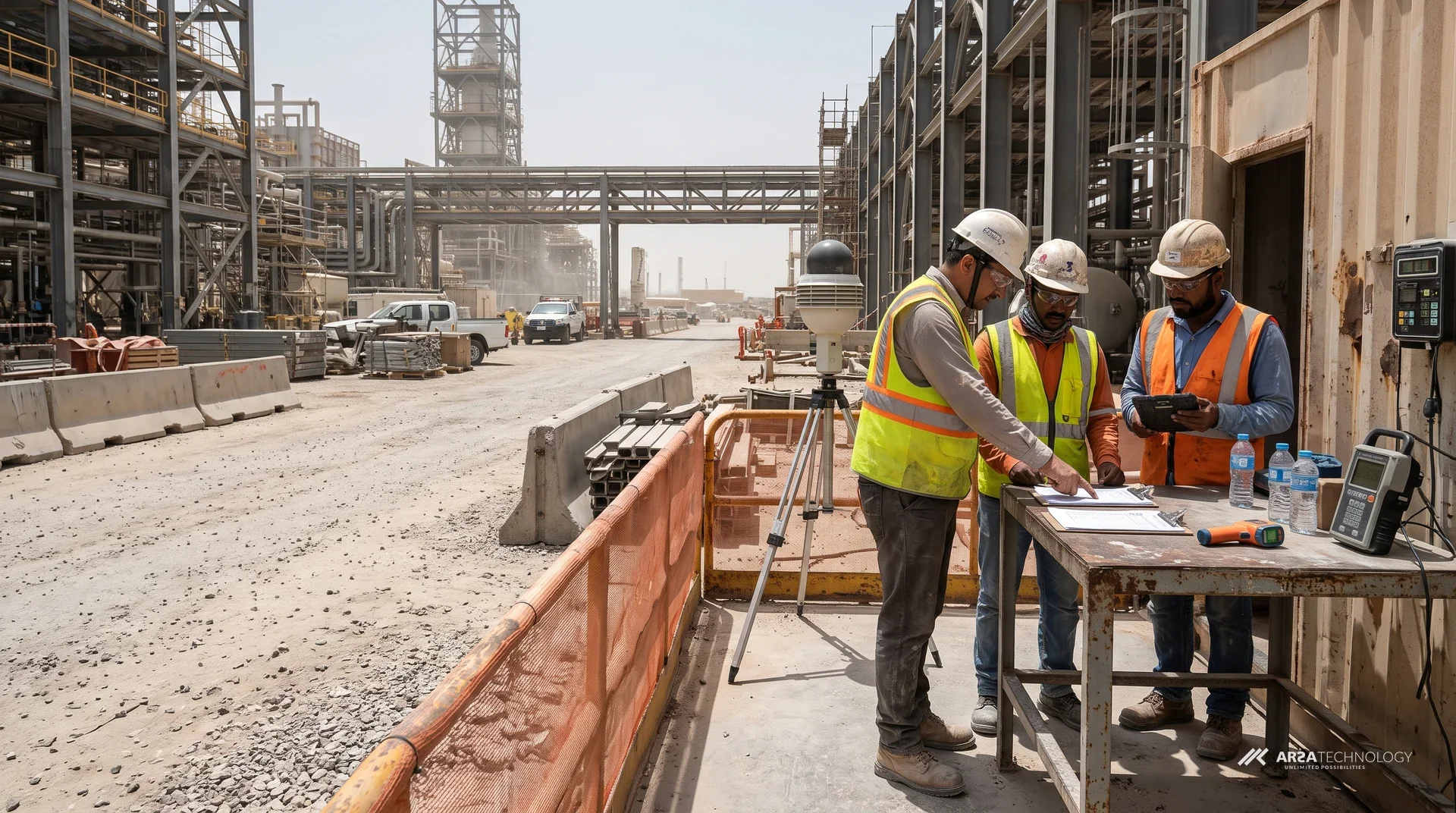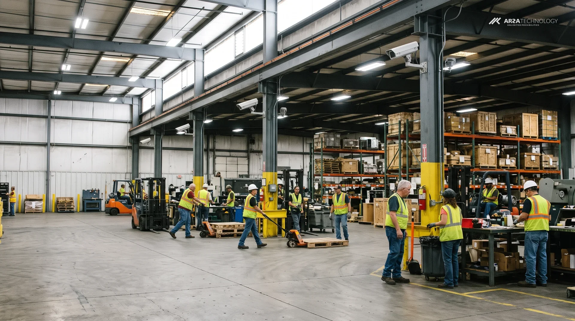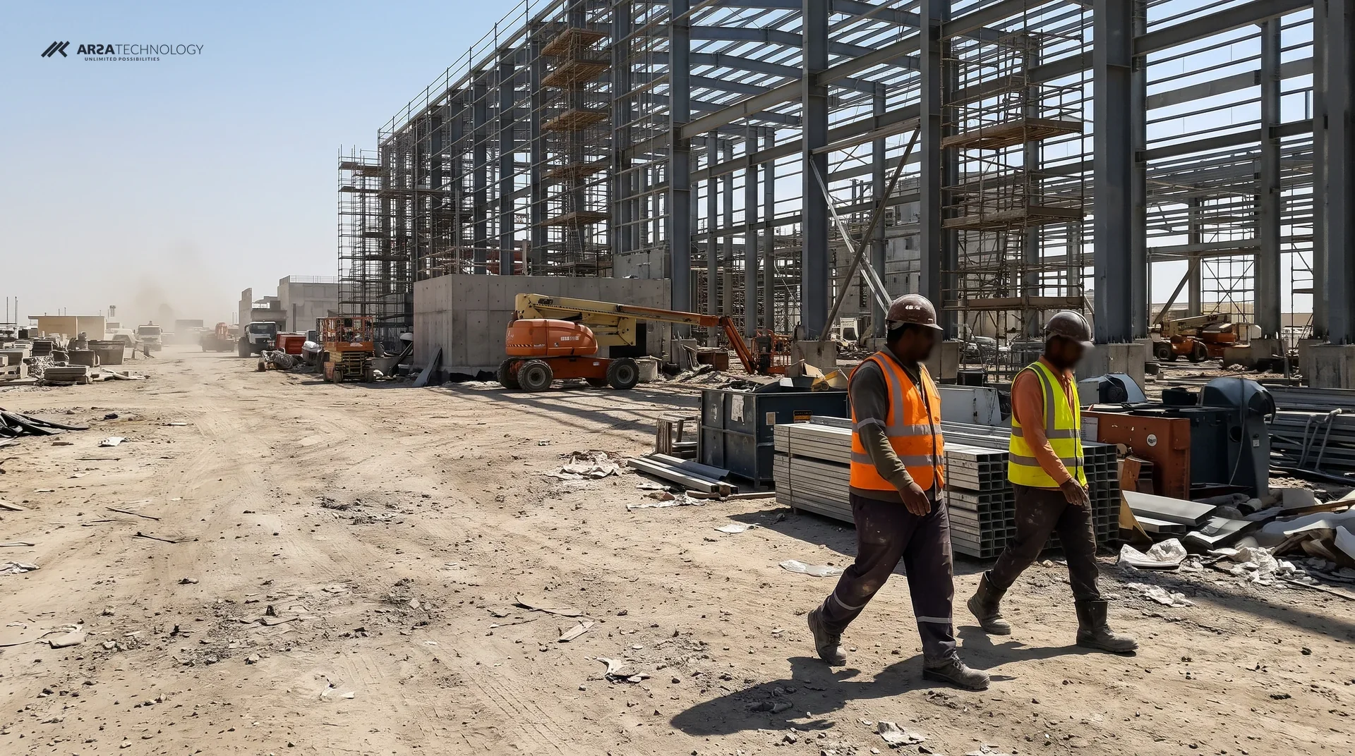

By the end of this guide you will have a survey of every camera on your construction site. For each one you will have its mount height, standoff, tilt, pixel density and light level, and a verdict of pass, fix or drop for helmet, vest and exclusion zone checks. On a mid-sized site the walk takes about a day, and the measurements decide what hardware you need. Without them, the hardware you choose ends up deciding which cameras work.
Read As Text
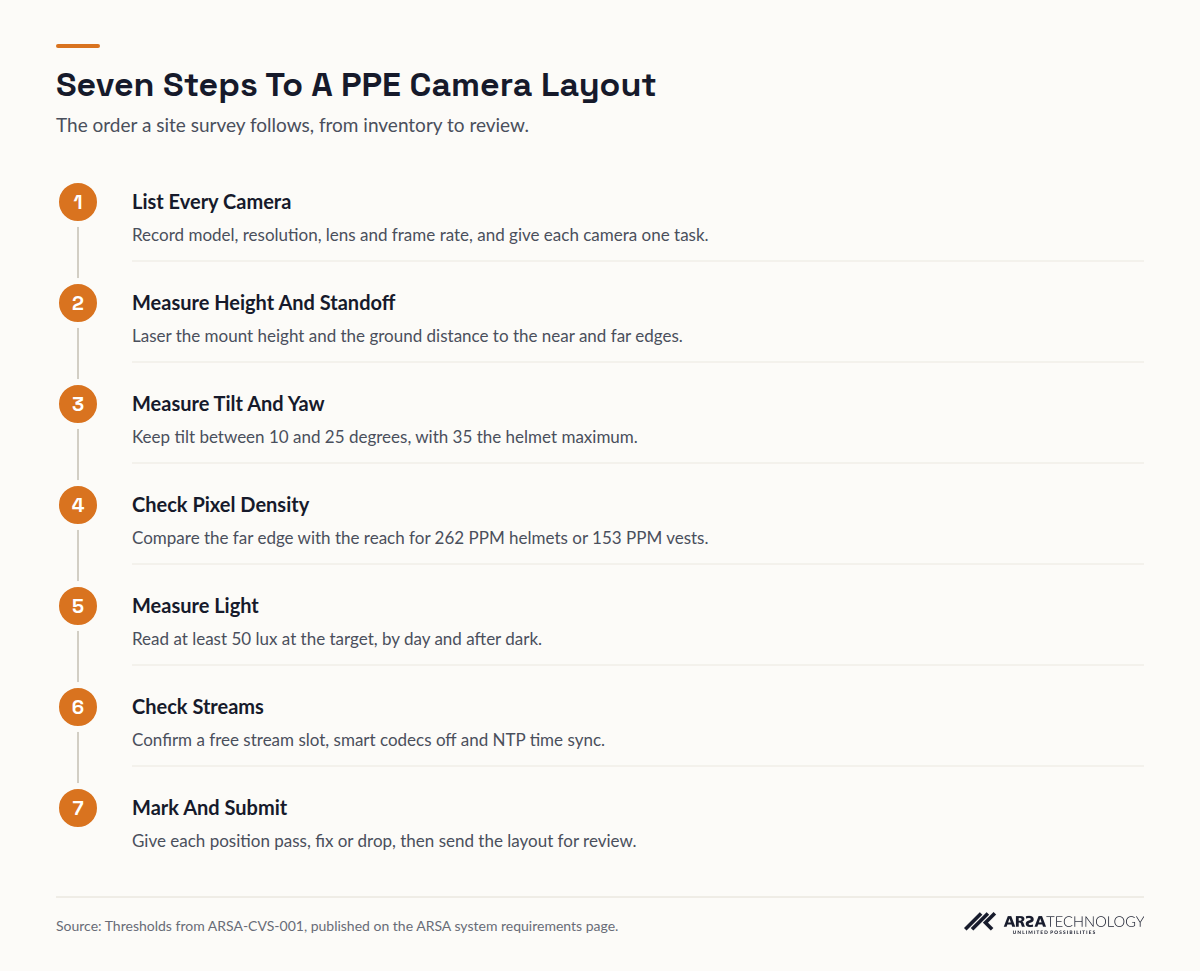
- List Every Camera Record model, resolution, lens and frame rate, and give each camera one task.
- Measure Height And Standoff Laser the mount height and the ground distance to the near and far edges.
- Measure Tilt And Yaw Keep tilt between 10 and 25 degrees, with 35 the helmet maximum.
- Check Pixel Density Compare the far edge with the reach for 262 PPM helmets or 153 PPM vests.
- Measure Light Read at least 50 lux at the target, by day and after dark.
- Check Streams Confirm a free stream slot, smart codecs off and NTP time sync.
- Mark And Submit Give each position pass, fix or drop, then send the layout for review.
PREREQUISITES
Before You Start
You need a few tools, the right access and two people. The survey is mostly measuring, and nothing in it needs a camera moved or a cable touched.
- The site's camera schedule, or the NVR's device list, with model numbers.
- A laser distance meter and a digital angle gauge (an inclinometer app on a phone held against the housing will do for a first pass).
- A lux meter, for readings at noon and again after dark.
- Read access to each camera's web interface or the VMS, to check resolution, frame rate, codec and stream settings.
- A site plan showing where helmets and vests are mandatory, and the exclusion zones around cranes, excavations and working plant.
- Permit to work at height if anyone must reach a camera on scaffolding or the crane. Measure from the ground wherever you can.
- A second person to stand in the target zone wearing a helmet and vest while you look at the live view.
- Sign-off from whoever owns data protection. Recording people is personal data under UK GDPR, and in the UAE it falls under the Personal Data Protection Law (Federal Decree-Law No. 45 of 2021). The survey usually needs short sample clips, and those should be cleared before you export them.
The figures below come from ARSA-CVS-001, the published camera and site standard on the system requirements page. They give measurable thresholds for each detection task, and that makes them useful whichever vendor you choose.
INVENTORY
Step 1: List Every Camera And Give It One Job
Write down every camera and the single task you expect it to perform: helmet check, vest check or exclusion zone. A camera's job sets the threshold it is measured against, so you have to decide the job before you take any measurements.
Record the model, resolution, lens focal length or field of view, frame rate and streaming protocol. The standard's floor is 2 MP at 15 fps over RTSP or ONVIF Profile S, and it recommends 4 MP at 25 fps. Cameras on site for security are often mounted high on scaffolding, poles or the crane. Mark those now, because Step 3 usually fails them for PPE even when they still cover an exclusion zone well. The step is done when every camera row has one task in it. If a camera has two tasks, give it two rows.
GEOMETRY
Step 2: Measure Mount Height And Standoff
Measure the camera's height above the ground and the horizontal distance from its base to the near and far edges of the area where workers must be checked. Those two distances set the working range that Step 4 tests.
Use the laser meter from the ground at the base of the pole or wall. Standoff is measured on the ground, so do not measure along the line of sight. Write down the far edge too, because pixel density is lowest there. The accepted reference case in ARSA-CVS-001 is a camera at 3.5 m with a 6.0 m standoff. If your numbers are close to that, you are probably in good shape. If the camera is much higher, keep in mind that a 6 metre mount cannot check helmets closer than about 7 metres from its own base.
ANGLE
Step 3: Measure Tilt And Yaw
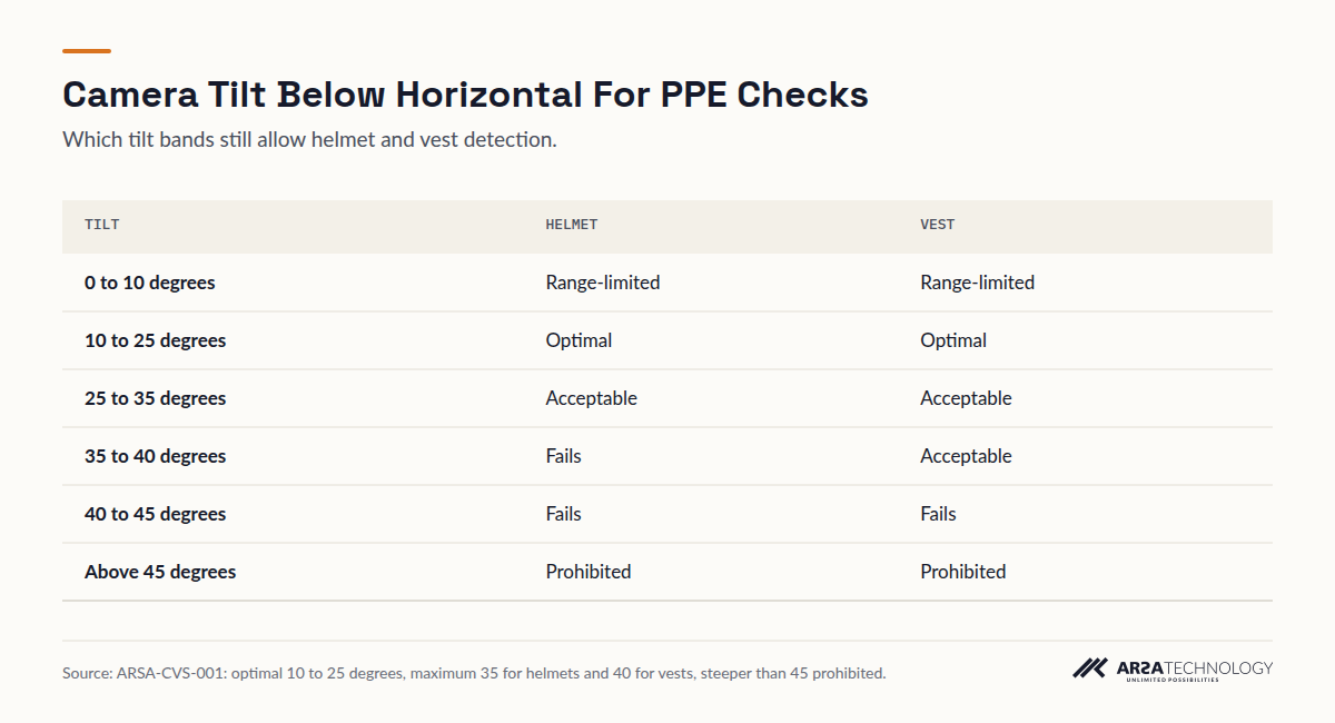
Measure how far the camera looks down below horizontal, and how far it looks across the path workers take. For PPE the optimal tilt is 10 to 25 degrees. The maximum is 35 degrees for helmets and 40 for vests, and anything steeper than 45 degrees is prohibited.
Hold the angle gauge flat on the camera housing along the lens axis. A steep camera sees the top of a helmet and very little else, because the wearer's own body hides the vest front. Yaw matters as well. The standard caps yaw for PPE at 45 degrees, so a camera looking side-on at the walkway misses the vest front entirely. This is the step that most often fails, so check it against the bands below before you go further.
View The Data
| Tilt | Helmet | Vest |
|---|---|---|
| 0 to 10 degrees | Range-limited | Range-limited |
| 10 to 25 degrees | Optimal | Optimal |
| 25 to 35 degrees | Acceptable | Acceptable |
| 35 to 40 degrees | Fails | Acceptable |
| 40 to 45 degrees | Fails | Fails |
| Above 45 degrees | Prohibited | Prohibited |
RESOLUTION
Step 4: Check Pixel Density At The Far Edge
Compare each camera's far-edge distance from Step 2 with the reach its resolution allows for its task. If the far edge is beyond that reach, the camera fails at that distance however good the software is.
Pixel density, written as PPM (pixels per metre), is the number of pixels the camera puts across one metre of the scene where the worker stands. It falls as distance rises. The reach figures below assume a standard 60 degree lens. A narrower lens roughly doubles every reach and halves the width covered, and the lens field of view visualizer lets you test a different lens before anyone changes one.
| Requirement | Helmet | Hi-Vis Vest | Exclusion Zone |
|---|---|---|---|
| Pixel density at target | 262 PPM | 153 PPM | 71 PPM |
| Reach, 2 MP, 60 degree lens | 6.3 m | 10.9 m | 23.6 m |
| Reach, 4 MP, 60 degree lens | 8.4 m | 14.5 m | 31.4 m |
| Optimal tilt | 10 to 25 degrees | 10 to 25 degrees | 15 to 40 degrees |
| Maximum tilt | 35 degrees | 40 degrees | 55 degrees |
| Minimum light at target | 50 lux | 50 lux | 10 lux |
Source: ARSA-CVS-001, published on the system requirements page.
Check the result on the live view. With your colleague standing at the far edge, the helmet should read clearly as a hard hat and not as a cap or a shape.
LIGHT
Step 5: Measure Light At Noon And After Dark
Take a lux reading at the target zone, held at worker height and facing the camera, once in daylight and once at the darkest working hour. PPE checks need at least 50 lux, and exclusion zones need 10 lux after dark.
Vest detection depends on colour. Under infrared the camera produces a monochrome image, so night shifts need white light on the zone, and infrared is unsupported for vests. On Gulf sites, also note strong backlight and glare at the gate during the afternoon. Check each camera's rated operating temperature against your summer conditions: the standard sets a minimum range of minus 10 to plus 50 °C and recommends minus 20 to plus 60 °C, with IP66 and IK08 for outdoor cabinets.
STREAMS
Step 6: Check The Stream Settings And Network
Open each camera's settings and confirm it can give an analytics system a clean stream of its own. Many cameras ship tuned for recording, and several of those settings degrade detection while looking fine on a monitor.
Confirm that the camera has two concurrent stream slots free, since the recorder usually takes one. Turn smart codecs such as H.264+ off on the analytic stream, set constant bit rate, remove privacy masks from that stream, and sync time to NTP with less than one second of drift. Pull the stream from the camera itself wherever possible, because many NVR re-streams are transcoded and drop frames. An NVR main-stream RTSP re-stream is accepted after the Camera Design Review confirms it is not transcoded. Then find where the compute will sit. The standard asks for a UPS with at least 15 minutes of hold-up and a location under 35 °C with clear airflow. On a Gulf site that means a temperature-controlled room or enclosure, and a portable site office will not meet it.
VERDICT
Step 7: Mark Each Position Pass, Fix Or Drop, Then Submit The Layout
Give every camera row one verdict and the remedy that would change it. Then send the layout for review before any hardware is ordered.
A fix is specific: a longer lens, a lower mount, a step closer to the gate line, added white light, or a second camera. A drop means that position cannot do the task at any sensible cost, and the zone needs a new camera. Attach a 30 to 60 second clip from each camera with a person in the zone, along with your measurements. The step is done when each row has a verdict and a reviewer can follow the reason for it without visiting the site.
PITFALLS
What Goes Wrong And How To Spot It
The most common failure is a camera mounted high for tamper protection and then pressed into PPE work. You can spot it in the live view because you see helmets from above and never see a vest front. Its tilt reading will be over 35 degrees. These cameras usually still serve exclusion zones well, since those allow up to 55 degrees, so give the PPE job to a lower camera placed further back and keep the high one for the zone.
The second failure is a camera whose angle is right but whose range is too long. At the near edge it looks fine and at the far gate line it fails, because pixel density halves each time the distance doubles. The fix is a longer focal length or a second camera. Tuning the model cannot fix it. Third, readings taken in the day pass and readings taken at night fail, so surveys done only in daylight give a false pass on vest checks for night shifts. Finally, a layout drawn at slab level can change within weeks as the frame rises. Re-survey any camera that is moved, because a position accepted earlier can drop below the density helmet checks need.
WHERE ARSA FITS
Getting The Layout Reviewed
If you want a second pair of eyes on the survey, ARSA runs a Remote Camera Design Review. It takes about one week, covers up to 20 of a site's cameras, and returns a pass or fail with a remedy for every position before any hardware ships. Larger sites can have an On-Site Camera Survey of up to 50 cameras. For Gulf contractors in the UAE, Saudi Arabia and Qatar, the Gulf Safety Pack starts with that review. It then runs PPE and exclusion zone checks on the existing cameras, with processing on site and the video kept in the country, and one head office dashboard covering several sites. ARSA delivers outside Indonesia. Where visa conditions prevent its engineers travelling, a qualified local partner installs under ARSA supervision. No accuracy figure is promised until the site's own positions are validated.
FAQ
Camera Layout For PPE Detection FAQ
Can I Use My Existing CCTV Cameras For PPE Detection?
Often yes, if each camera meets the distance, angle and light thresholds for its task. A 2 MP camera with a standard 60 degree lens can check helmets out to 6.3 m and vests out to 10.9 m, and it covers an exclusion zone to 23.6 m. The survey above tells you which of your cameras can do which task.
What Height Should A PPE Detection Camera Be Mounted At?
There is no single height, because height and standoff work together. The accepted reference case is 3.5 m high, 6.0 m from the zone and tilted 22 degrees. A higher mount must sit further back to keep the tilt at 35 degrees or less for helmets.
Should I Upgrade To 8 MP Cameras To Be Safe?
Not by default. Higher resolution increases reach, but each pixel collects less light, so an 8 MP camera can perform worse than a 4 MP camera in a dim area. A longer lens on a 4 MP camera is often the stronger choice for scenes that must work at night.
Does Vest Detection Work At Night Under Infrared?
No. Infrared produces a monochrome image, and vest detection relies on colour. Night shifts need white light at 50 lux or more on the zone.
Why Survey Before Choosing Hardware?
The survey decides how many cameras, which lenses and how much compute the site actually needs. If you order equipment first, you may later find that half the positions cannot resolve a helmet. Correcting that after installation means new mounts, new cabling and lost weeks.
Further reading: see how this is applied on a live project in AI video analytics for construction sites. If you would like an engineer to check a few clips from your own cameras, start with a free AI assessment.